テクニカルインフォメーションTECHNICAL INFORMATION
 カムシャフト装着時には、作業手順の不備による折損にご注意ください。
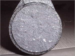
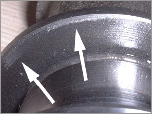
カムシャフト折損時に、製品の状態が以下の写真同様の場合、そのすべてが作業ミスによるものです。
 |
 |
| 折損面 | ジャーナルスラスト軸受け部 |
|
折損面にはす穴等の異常はなく、正常
|
前面アルミ痕、エッジ部分にかじり痕あり
|
| スラスト軸受け前面アルミ痕、エッジ部分かじり痕は、カムシャフト製作過程、カムシャフト作動時において付く様なものでは無く、カムシャフト組み込みの際、ジャーナルがしっかり収まっていないまま組み付けてしまった場合のみ残る痕です。したがって、ジャーナルの収まりの悪いまま組み付けたことにより、カムに負担がかかり破損したものと考えられます。 | |
 カムシャフト組み込み時には以下の点にご注意ください。
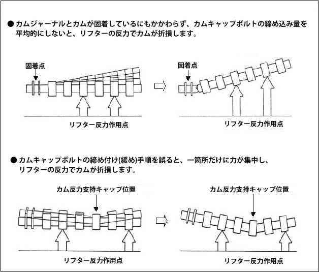
カムシャフトを組む際、カム山がリフトしている所を基準にしながら、できる限りカムシャフトがヘッド面に水平に沈む様、均等に少しずつカムキャップボルトを締めてください。

 CAUTION; Improper installation can cause breaking / damaging camshaft.
Broken / damaged camshafts shown in below pictures are all caused by improper installation.
 |
 |
| Fracture surface | Journal thrust bearing brim |
|
No cavity is appeared on fracture surface
|
Gouged “Aluminum” mark on surface, galling mark on edge
|
| These gouged mark and galled mark can only be seen when the camshaft is installed while the journal(s) is improperly sitting. Assembling forcibly while journal(s) is not fit in right place can stress the entire camshaft and cause breaking / damaging it. | |
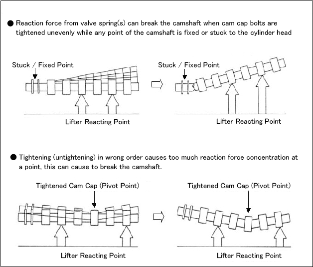
 Be aware of following common mistakes.
Check the most lifted point and tighten the cam cap bolts evenly, little by little to keep the camshaft as horizontal against the cylinder head as possible.


